Firebox Construction & Detail
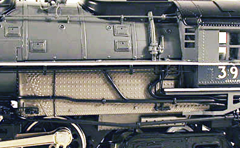
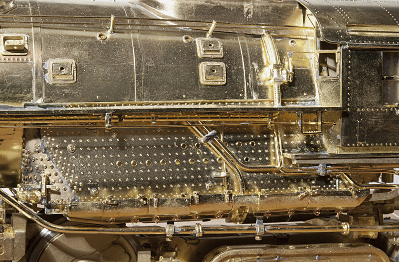
One of the commonly overlooked areas of a model steam locomotive in terms of detail and construction accuracy is the firebox, this may in part be due to a lack of knowledge regarding prototype locomotives. The photo above shows a typical O scale model firebox, compare the photo above to the one below and see what differences you can discern. The models are both Union Pacific Challengers, the top model is a previously produced offering, the model on the bottom is our Kohs & Company first sample model prior to corrections.
Lets consider some of the factors that should be considered in evaluating the firebox accuracy of our subject models and models in general. The basic sheeting of the firebox above has no contour, top to bottom or front to back, it is a flat sheet which would be very uncommon for a prototype. The front corner is a folded square corner with the front of the firebox left open, which eliminates any detail that should be present in that area. In the photo below you can see a radiused contour along the bottom edge of the firebox sheet and the leading edge of the sheet is contoured to meet the front casting used to accurately replicate the front corner of the firebox. This approach to construction accurately replicates the general appearance as well as the seam and overlap of materials of the prototype in this area. The staybolt caps at the front of the firebox sheeting on the top model are very undersized as a result of the limitations of photo etching the detail. The corresponding detail on our model has scale proportions as a result of using a casting to create the prototypically radiused corner with the proper sized staybolt cover detail included.
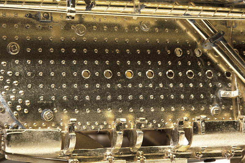
The staybolts modeled on the firebox sheeting were again photo etched on the top sample which gives them a square-shouldered appearance. On the Kohs & Company model, the staybolts have the correct 'lip' radius with a recessed center which correctly models the hollow core staybolts used on the Challenger, this can be seen in the close up photo below.
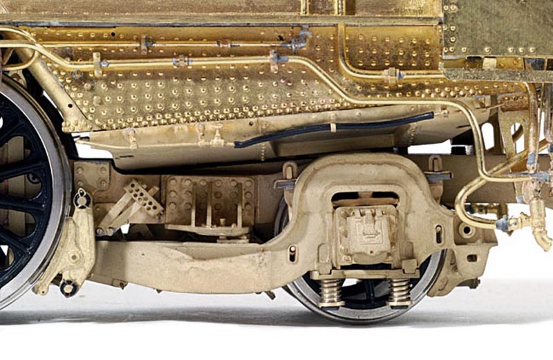
Why are the two approaches used in modeling? The main reason is certainly cost of production based on required hard-tooling, the number of parts to produce and the number of parts to assemble and finish. To create the firebox on the top sample there is one sheet for each side of the firebox with one fold and a photo etch pattern to be created. The firebox on the Kohs & Company model has a base sheet for each side which must be contour formed with tooling, the corner castings which must be mastered, duplicated and then assembled. Additionally, the punch tooling to create the staybolt pattern, breather and assemble holes must be built and then utilized to create the unique sheets for each side. When there are multiple model versions with variations in the firebox configuration, unique tooling must be created for each variation. On our model each circulator plug is hand soldered in place to achieve the correct detail and relief, to do otherwise is a compromise, these details can be seen in the photo above.
You have to judge for yourself the effectiveness of the two approaches to modeling and determine what is important to you. As with many details and features, customers often do not immediately notice firebox deficiencies, but once they do, they are extremely difficult to ignore. As the final arbiter in selecting models for purchase, you have to decide at what price point compromise is no longer acceptable. In developing a tier-one project, close attention has to be paid to the exact components used on subject prototypes so that they can be correctly modeled, a staybolt on a Union Pacific Challenger is not the same as a staybolt on a 'Pennsy' K4 as shown below.
Copyright © 1997- 2024 Kohs & Company Inc, All Rights Reserved